%20with%20Pre-%20%26%20Headphone%20Amplifier%20(Black)?unique=dcc2058)
%20with%20Pre-%20%26%20Headphone%20Amplifier?unique=8ff3e74)
%20with%20Pre-%20%26%20Headphone%20Amplifier?unique=8ff3e74)
%20with%20Pre-%20%26%20Headphone%20Amplifier?unique=8ff3e74)
%20with%20Pre-%20%26%20Headphone%20Amplifier?unique=23addd6)
%20with%20Pre-%20%26%20Headphone%20Amplifier?unique=23addd6)
%20with%20Pre-%20%26%20Headphone%20Amplifier?unique=23addd6)
%20with%20Pre-%20%26%20Headphone%20Amplifier?unique=23addd6)
%20with%20Pre-%20%26%20Headphone%20Amplifier?unique=23addd6)
%20with%20Pre-%20%26%20Headphone%20Amplifier?unique=23addd6)
%20with%20Pre-%20%26%20Headphone%20Amplifier?unique=23addd6)
%20with%20Pre-%20%26%20Headphone%20Amplifier?unique=23addd6)
%20with%20Pre-%20%26%20Headphone%20Amplifier%20(Black)?unique=dcc2058)
%20with%20Pre-%20%26%20Headphone%20Amplifier?unique=8ff3e74)
%20with%20Pre-%20%26%20Headphone%20Amplifier?unique=8ff3e74)
%20with%20Pre-%20%26%20Headphone%20Amplifier?unique=8ff3e74)

%20with%20Pre-%20%26%20Headphone%20Amplifier?unique=23addd6)
%20with%20Pre-%20%26%20Headphone%20Amplifier?unique=23addd6)
%20with%20Pre-%20%26%20Headphone%20Amplifier?unique=23addd6)
%20with%20Pre-%20%26%20Headphone%20Amplifier?unique=23addd6)
%20with%20Pre-%20%26%20Headphone%20Amplifier?unique=23addd6)
%20with%20Pre-%20%26%20Headphone%20Amplifier?unique=23addd6)
%20with%20Pre-%20%26%20Headphone%20Amplifier?unique=23addd6)
%20with%20Pre-%20%26%20Headphone%20Amplifier?unique=23addd6)
Audio-GD - R28 mk3 R2R DAC (PCM / DSD) with Pre- & Headphone Amplifier
R28 mk3 offers two gain modes: 12dB in low gain, ideal for driving headphones with over 95dB sensitivity, and 22dB in high gain, paired with strong power output, sufficient to drive headphones like the HE6, which has around 85dB sensitivity. If customers wish to boost the gain by 6-12dB, the total gain can be increased to 28-34dB.
There are 4 digital (USB, Coaxial, Toslink, and I2S) and 1 pair analogue balanced XLR inputs availale. In total 3 analogue outputs, RCA, XLR and ACSS (ACSS is Audio-GD proprietary output) and on frontpanel there are 2 headphone outputs, a 6,3mm Jack (unbalanced) and 4-PIN XLR (balanced connector.
| Brand: Audio-GD |
| Product Type: Amplifiers with DAC |

AUDIO-GD R28 MK3
FEATURES
- Complete seperation and isolation between digital and analog circuits.
- Real balanced discrete transistors headamp / preampamps and DAC all in one model
- Headamp can output max 9500 mW, in fact, it can drive even most difficult headphones .
- Two gain modes, the 12DB on low gain for drive the headphone which has over 95DB sensitivity, and 22DB on high gain, enough to drive the HE6 Hifiman headphone.
- Dual transformers power supply separately, built in 10 ground ultra speed linear PSUs and two ground pure class A PSUs
- True balanced DAC design ,built in 4 group fully discrete real balanced DSD native decoders , 8 group fully discrete R-2R PCM decoders, supports up to 32bit / PCM384K /DSD512.
- Unique USB design, the USB interface uses the centrla Accusilicon master clocks for high precision timing becuase there is only 1 master clock active, this improves USB sound quality drastically.
- 8x discrete R-2R DA Converter circuits
- 4x Discrete native DSD decoders circuits
- Amanero USB interface up to 384 kHz PCM / 512x DSD native
- All digital inputs are isolated.
- Discrete dc-coupled current signal transmission design without opamps
- Eas firmware update to support future improvements and features
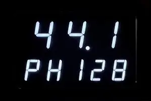
Multi-Functional Display
A new display type has been added to the R8 mk3. Both input and sample rate are now being displayed. (2 line multi-function display)

Firmware Update Port
On the back-panel of the unit an update port is available to quickly update the firmware using the USB Blaster (included).
FPGA Signal Processing
The internal hardware design is fully controlled by complex software. Software in the FPGA can easily be upgraded offering new capabilities or improve the performance of the device without replacing any hardware.
TECHNICAL SPECIFICATIONS
| SPECIFICATIONS | |
|---|---|
| Type | Pre-amplifier / Headphone amplifier with integrated R-2R DAC |
| Inputs |
|
| Outputs |
|
| SNR | >120dB |
| Gain | L mode : +12DB H mode : +22DB |
| Volume | 100 steps super exponential control |
| Channel Imbalance | <0.05dB |
| Frequency Response | 20Hz-20kHz 1Hz – 140kHz (-3DB analogue) |
| Output Level | Headphone output : 19V RMS (balance) Preamp Variable output : 19V RMS (balance) DAC Fixed output : 5 V RMS (balance) |
| Headphone Output (balanced) | 9500mW / 25 Ohm 8000mW / 40 Ohm 3500mW / 100 Ohm 1200mW / 300 Ohm 600mW / 600 Ohm |
| Output Impedance | ACSS : 1 Ohm DAC / Preamp : 5 Ohm |
| Input Sensitivity | 0.5Vp-p (75 Ohms, Coaxial) 19dBm (Optical) |
| Support OS | Windows (driver), OSX, Linux, ISO |
| Sample Rates | USB : 44.1kHz,- 384kHz / DSD64 – DSD512 (native) COAX : 44.1kHz, 48kHz, 88.2kHz, 96kHz, 176.4kHz ,192kHz Optical : 44.1kHz, 48kHz, 88.2kHz, 96kHz, 192kHz |
| Power | 220-240V AC50/60Hz |
| Power Consumption | 24W |
| Weigth | 7.6kg |
| Dimensions | 360 x 360 x 85 mm |
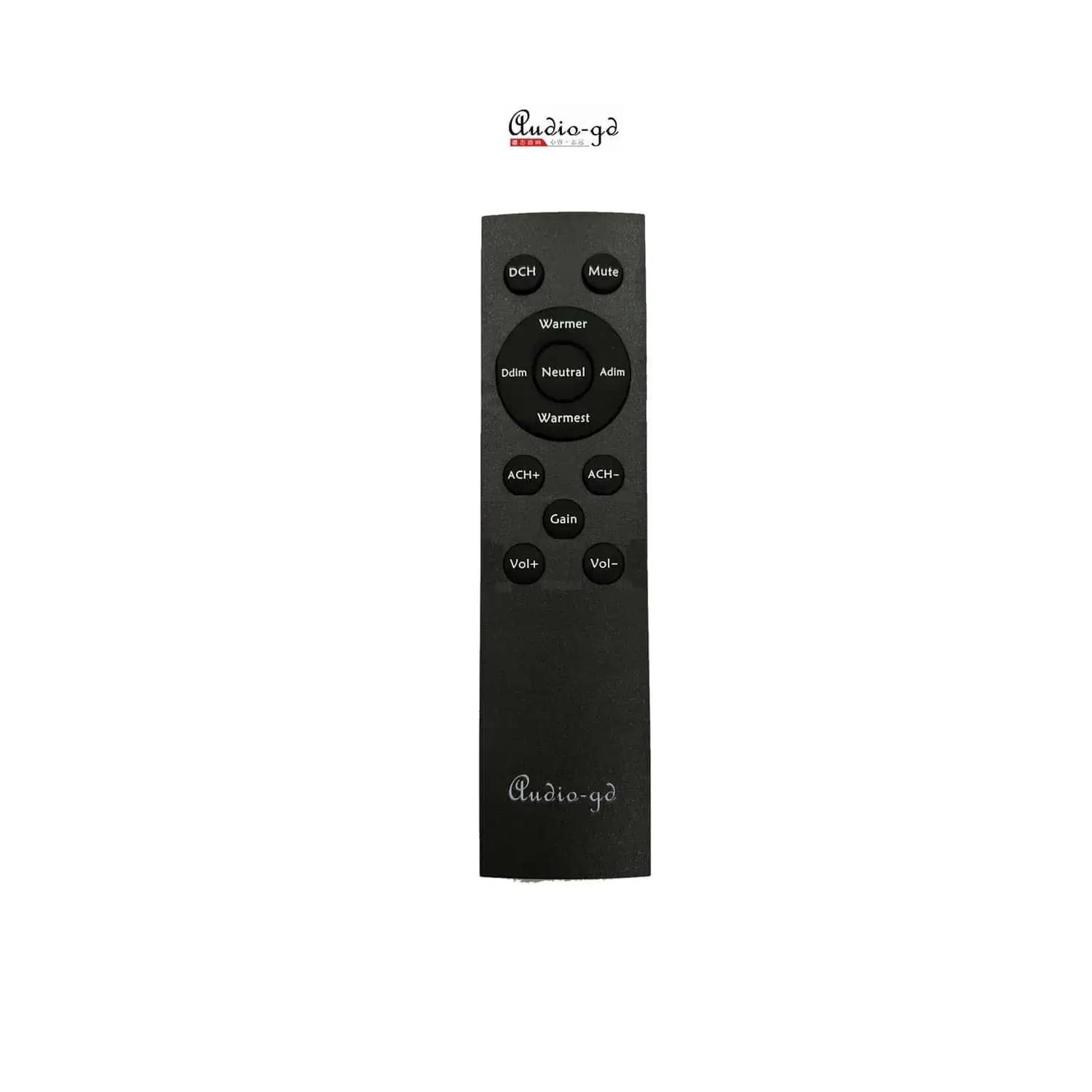
| Accessoires | IEC Power Cord x1 USB Cable x1 Remote Control x1 |
NOS & OVERSAMPLING MODE
The R8 offers several Oversampling or NOS (Non-Oversampling) modes. If you wish to choose Oversampling, simply select the value “O”. If you want to choose the NOS then you have to choose the value “N”. You can then select one of the following modes to adapt the playback to your listening experience
THE R-2R LADDER STORY
The R-2R DAC has become popular and was originally designed long time ago by MSB, and did not include the wonderful correction design of the modern MSB technology. In the High-End of the shelf (finished products) market, the R2R design is usually much more complex when outstanding performance is offered. Some manufacturers are using shift registers design to realize ladder compensation. A less complex, unfortunately also a less performing.
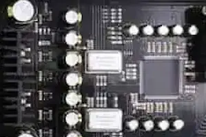
A far better design switches resistors in parallel mode; an ultra-fast FPGA chip controls and corrects the R2R ladder. The parallel design mode controls every bit respectively and therefore achieve unprecedented performance. (In parallel mode only 1 clock cycle is needed to output all data; serial design mode needs at minimum 8 up to 24 clock cycles) The parallel design is particularly complex, however when it is done properly it can correct every bit of the ladder. (Photo below shows a FPGA design with R2R ladder). With incredible speed and accuracy the R-28 will correct the unavoidable imperfections of the basic R2R ladder caused by tolerance of resistors; avoid glitches at ultra-high speed to deliver unrivaled musical performance.
TOLERANCE OF RESISTORS IN LADDER
Some manufactures claim to achieve good performance becuase they use lowest tolerance ladder resistors. The following calculation example will cover this. At 16 bit the tolerance of 1/66536, 0.1% (1/1000) it is by far not enough to achieve decent performance. Even using resistors with 0.01% (1/10000) tolerance, lowest tolerance available today,cannot deliver the desired performance This is just 16 bit, imagine a 24 calculation! To process 24 bit resolution it would require resistors with a tolerance of 0.00001%. This is purely theoretical; if this tolerance would exist the discreteness of the switch logic chips will already have too much internal impedance and will shake-up such design.The tolerance of the resistor will never solve Imperfections of a ladder.
The solution lies in the correction the ladder and not only depend on the tolerance of resistors. It’s a combination of both: Ultra-low tolerance resistors controlled by a correction technology using very high speed with parallel FPGA processing.
ULTRA FAST SIGNAL PROCESSING
FPGA stands for Programmable Array Logic. Nowadays the FPGA is widely adopted in audio devices. The internal hardware design is fully controlled by complex software. A huge advantage is the fact the software in the FPGA can easily be upgraded offering new capabilities or improve the performance of the device without replacing any hardware. Versatile and future proof design.
- High performance SPDIF interface, replacing traditional less good performing SPDIF interface chips like DIR9001, WM8805 or AK411X,etc.
- Full re-clocking process with FIFO design applicable on all inputs. This way the output data keeps fully synchronized with the clock signal to reject any jitter.
- Built in 2X, 4X and 8X oversampling and digital filters and on top of this 4 different true NOS (only analog 6dB filtering) modes. To completely configure the sound according to your taste.
ANALOGUE OUTPUT STAGES
The analog output stages are as important, they have a tremendous influence on the final sound quality. After d/a conversion by the R2R D/A modules the analogue signal is transported by fully discrete matched-transistor output stages; DC-coupled design with first class through-hole components. No SMD compon ents are applied in the analogue section. The high speed unique ACSS ((Audio-gd Current Signal System) output stages are non-feedback and current driven. Unique performance because almost all other designs need to convert the signal multiple times from and to current and/or voltage, resulting in less detailed and less transparent sound-stage The output buffers are single ended FET; two stages in parallel to reach very low output impedance. All output stages are in pure class A without (negative) feedback to achieve purest and a real live sound reproduction. The 4 OPA op-amp’s are DC servos, this way no coupling-capacitors are needed and DC output is automatically biased. The listener will be presented a strikingly transparent and neutral sound.
ACSS – Current Amplification
Audio-GD has developed an advanced current-driven amplifier technique. Also known as ACSS, Audio-GD Current System Signal. This special technique ensures that the signal travels a much shorter path and that ensures a more transparent, faster and more neutral reproduction. A similar technique is used by, for example, KRELL. The Current Conveyor technology mostly components are the current mirror. The Current Conveyor technology isn’t a new technology, at 1966 , professor K.C. Smith and A.S.Sedra publish the concept “current mode analogue circuits “ .
HIGH PRECISION VOLUME CONTROL
Volume control consist of relay-controlled attenuators. Fully-independent, fully-balanced stereo volume controls. The volume controls feature consist of high-precision 0.05% tolerance film resistors and golden contact relays. Buffered inputs and outputs.There 4 channels volume boards are built in the unit to achieve ultimate balanced volume control. They are controlled by a digital signal controlling the high quality relays switching the precision resistors in analog area.
Quality of volume control is very important in balanced applications . It have to effectuate the four channels to work as synchronous as possible to keep the balanced signal in perfect shape. In traditional volume controls the balanced output will introduce distortion which will negatively influence sound quality and performance and might even get worse than a single ended setup and waste the advantages of balanced designed solution.
CLEAN POWER
The DAC consist of 2 tuned low noise, low flux leakage, R-cores transformers. In total 130W power to supply all digital parts and the left and right analog boards. The DC power is distributed over several separate power regulators. Analogue stages are pure class A low noise shunts; fed by 3 groups linear power supplies. Resulting in ultra-high speed and clean power for all individual parts.