


Tech Talk
In Tech Talk we explain the technical side of our power supplies. For any questions like specifications, breaking in time, AC phasing, connections and usage, replacing the fuse, please read the Farad Super3 Manual. If you have any other questions, please contact us!
Using an ultra low noise regulator does not mean the supply is ultra low noise
The output noise of a supply is the result of the noise the supply introduces itself, unfiltered noise from outside, ground loop noise and the regulator noise. The first three measured not on a bench, but when the supply is in a system, are typically much higher than the last and must be addressed very seriously. The regulator takes care of only a real small part of the quality of the supply, there is much much much more to it than regulators alone. The regulator always damps only a limited amount of this noise in a very limited bandwidth, like around -100dB in the 100Hz region and only -50 dB at 10MHz max, and nothing anymore at higher frequencies, for the best ones on the market now (like LT3045). So making a good supply, especially in the for digital equipment very relevant > 10MHz Hf region is not at all about the regulator, but all about the supply itself.
We take great care not to induce noise (Ultra low Vf Schottky rectifiers, a special custom high inductance double shielded transformer, choke pi-filters, no SMPS or switching regulators) and in filtering noise from the outside (special starred PCB layout, common mode chokes, ultra-low ESR caps, supercaps). And off course we also use low noise regulators. There is a choice of many real good regulators on the market, all with their specific merits. We use a double regulation with two specially selected regulators, which together we found a real good combination. Together with their pre-, intermediate- and post Hf noise filtering, they are having less noise, better transient, lower output impedance and much better PSRR than any (even the LT3045) regulator on the market. We have chosen to optimize the system and not just one part. This is also why the Farad Super3 performs so well against any other supply.
What are super capacitors?
EDLC Super capacitors, also called ultra-capacitors or booster capacitors are the latest development in capacitor technology. They are based on a porous carbon material with very high surface area and very small layer distances, resulting in very high charge density. Super capacitors combine a very high capacitance with high pulse power capability and low ESR values. In short they act like batteries without their disadvantages.
Why do you use super capacitors?
Where typical large electrolytic capacitors have typical values up to 10.000uF, or 0.01F, even our 3A super cap supplies have a capacitance over 1F meaning 100 times more energy storage! Super capacitors can deliver high pulse currents and have low ESR, resulting in a very stable and clean, battery like, power input for the final low noise linear regulator. The better and more stable this input, the better the final result.
Is it true that supercaps have a short lifespan?
There seems to be some confusion about super capacitors and their lifespan. It is commonly said supercaps have a short lifespan. We think those people confuse the EDCL supercaps with the older gold”super”caps. EDLC supercaps are a new technology made for long life 24/7 operation, and are because of their very high capacitance and low ESR very suitable for buffering in power supplies and bypassing (for high current peaks) of batteries in car and other DC systems. They differ completely in technology from any other capacitor made before.
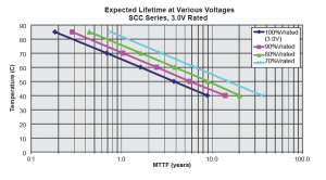
See the manufacturer curves for the capacitors we use in our designs. All capacitors in our designs will be below 80% of the rated voltage. Even at full load continuously the caps temperature will stay below 50 degrees. In practice the supply will be 40 degrees maximum at normal use (below 2A average). So lifetime expectancy according to the manufacturers curves will be worst case over 10 years, in practice more like 20 years.
Why are you using the super capacitor power bank as smoothing capacitors and do you not switch between one bank while loading the other?
There are several reasons why we do not do this. First it means extra switching electronics in the supply lines, second it means that the supply is using only half of capacity of the super caps at a time. Third and maybe most important, it means that the final regulator does not get a constant voltage at its input. One Farad of capacitance is the ability to deliver 1A of current for 1 second with 1Volt drop. Say there is 10F of super caps at 3A load, this means the voltage drops 1V in 3 seconds. The regulator needs its minimal voltage input, so there needs to be a bank switch every 3 seconds, so the final regulator gets a saw tooth signal with 1V amplitude of 0.3Hz.
This influences the output characteristics of the regulator, and therefore the output power quality. And even with these switching circuits the AC ground loops never will be avoided, since there always is a coupling through earth, unless relays are used, and even then statically.. In our supplies we use double static shielding in the transformer, choke smoothing and pre-regulation before the supercapacitor banks, noise residue and ground loops will be minimal and also the necessity for switching.
Why do your supplies only have one fixed output voltage?
The power dissipation of a linear regulator is dependent on the ingoing and outgoing voltage and current. Therefore the only way to make the output flexible is to make the input voltage flexible or by using switching power regulators, as many other brands do. Both of these ways are very sub-optimal designs. Since we are aiming to be the absolute reference in linear regulated power supplies, we specifically choose to go for rigid, but fully optimized fixed output voltage in our power supplies.
What is the importance of star grounding and star configuration power supply?
When two electrical points are connected to each other, the connection between them never is perfect and will always have inductance, capacitance and resistance. When current is drawn through this connection (whether it is wire, PCB trace or point to point), a voltage will be induced, adding noise to the signal. The presence of these problems can be heard when disconnecting interlinks between devices as loud plops, squeezing and buzzing. Although almost always present, it is not normal and a good system does not have these noises.
By starring ground lanes and power lanes, the distance of the connecting lines will be reduced to zero inside the device and thus also the induced noises. A supply can measure really good on a test bench, but when not properly starred, it will give a lot of additional noise in a system.
Why do you not use power line filtering?
A good power supply is in fact just a power line filter. We use specially custom wound shielded high inductance toroidal transformers. By adding chokes and fast filtering capacitors around it, we already have better initial power input, without adding additional components in the signal chain, keeping things more simple and better.
What protection do the Farad power supplies have?
Most commercial linear and SMPS power supplies will give out full voltage when their final regulator, or parts around it break down. This will almost certainly result in heavy damage of the device to which is connected to it. Farad power supplies are not only protected against the usual things like shorts, over-temperature and over-current, but also have a microprocessor controlled crow bar protection against over-voltage. In short this means the supply will short itself and blow its own fuses when a dangerous too high output voltage is detected, so the load will never be damaged.
Why do you use gold plated 4 pin GX16 output connectors?
Output impedance of a power supply is really important. A total output impedance of 100 mOhms (typical in many commercial power supply systems), already gives a voltage drop of 300mV when the load changes from 0 to 3A. This means bad regulation, and off course needs to be as minimal as possible. Output impedance is made up by the regulator, the PCB traces, connector and cables. We choose a low impedance, high transient, low noise output regulator. On the PCB we use power planes, so wide organic shaped traces. We do not like to use barrel (or alike low level quality) connectors, since they have high contact resistance, typically in the order of 30 mOhms. Instead we use the gold plated GX16 4-pin connector, gold plated GX16 connectors have a typical contact resistance of 3 mOhms, and with two pins parallel this is even halved, giving much lower total output impedance.