


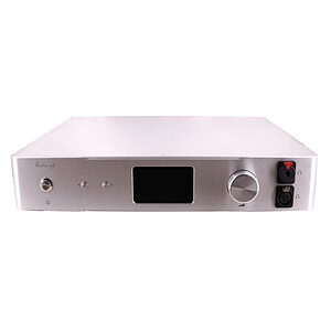
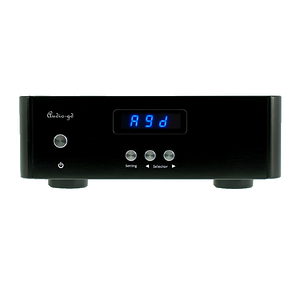
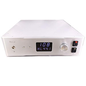
Audio-GD – R7 MK2 – Discrete Balanced R2R Ladder FPGA Accusilicon DAC – PCM / DxD / DSD
€2.846,- ( €2.352,07 excl. VAT)
The first R7 was launched 4 years ago and immediately received the BLUE Moon award from 6Moons! This was the first generation discrete R2R ladder DAC developed in-house by Audio-GD. Thanks to the use of the programmable chips (FPGAs), constant improvements could be made with a software update!
Unique R2R correction technology. Digital signal processing driven by high-speed FPGA supporting FIFO buffering and re-clocking. Software up-gradable design enables future new capabilities and improvements.
Nicht vorrätig
- Cheaper elsewhere? Contact us!
- More than 10 years of experience
- Products are shipped from Netherlands (EU)
- Outside EU pay excluding VAT price
- EU citizens pay including VAT (No custom fees)
- Premium service (trustpilot)
REVIEWS
 |
 |
 |
R7 mk2 HIGHLIGHTS
The first R7 was launched 4 years ago and immediately received the BLUE Moon award from 6Moons! This was the first generation discrete R2R ladder DAC developed in-house by Audio-GD. Thanks to the use of the programmable chips (FPGAs), constant improvements could be made with a software update!
In addition to software improvements, the mk2 has also received a major hardware upgrade. The improvement is quite obvious compared to the previous generation.
SPECIFICATIONS
| Specifications tested by OS8 mode in optimal conditions. Systems are tuned to improve sound quality, this may impact the specifications below. | |
| S/N Ratio | >120DB |
| Output impedance | <5 ohm (XLR ,RCA) |
| Output Level | 2.5V (RCA) 5V (XLR) 2+2MA (ACSS) |
| Frequency Response | 20Hz – 20KHz |
| THD | <0.01% |
| Input Sensitivity |
0.5 Vp-p ( 75 Ohms, Coaxial ) |
USB OS Support |
Windows, OSX, Linux, ISO |
| Sample Rates | USB / I2S mode: 44.1kHz – 384kHz /32Bit USB / I2S mode:DSD native 64-512 AES & Coaxial mode: 44.1kHz – 192kHz /24Bit Optical mode: 44.1kHz – 192kHz /24Bit (Most optical sources only support up to 96K 24BIT) |
| Power Requirement |
Version 1: 100-120V AC 50/60 Hz |
| Power Consumption | 23W |
| Package Weight | Approximately 15KG |
| Dimensions | W430 X L430 X H93 (MM, Fully aluminium ) |
| Accessories | AC power cord X1 USB cable X1 |
MAGNA R2R SILVER UPGRADE
We, Magna Hifi, have been working for months on possible improvements for Audio-GD R2R DACs. Because we have gained a lot of experience with the Mano streamer, we had certain ideas about how things could be improved and sound better. AND IT DOES! Magna R2R Silver upgrade includes Internal board to board wiring replaced by solid core silver wiring with cotton insulation After the modification the R2R DAC sounds cleaner; and the edges will become softer better and more spacious sound image.
ABOUT THIS DAC
DIGITAL SETTINGS (OVERSAMPLING & NOS)
The R-7HE offers several Oversampling or NOS (Non-Oversampling) modes. If you wish to choose Oversampling, simply select the value „O“. If you want to choose the NOS then you have to choose the value „N“. You can then select one of the following modes to adapt the playback to your listening experience.
DSP SETTINGS |
||
Oversampling |
||
| Oversampling | Passband Filter | |
| Mode 0 | 1x Oversampling | -130dB digital |
| Mode 2 | 2x Oversampling | -130dB digital |
| Mode 4 | 4x Oversampling | -130dB digital |
| Mode 8 | 8x Oversampling | -130dB digital |
Non Oversampling (NOS) |
||
| Mode 1 | FIFO Data processing | 6dB Analogue |
| Vinyl simulation mode | ||
| *Supports -50dB passband via PLL setting | ||
THE R-2R LADDER STORY
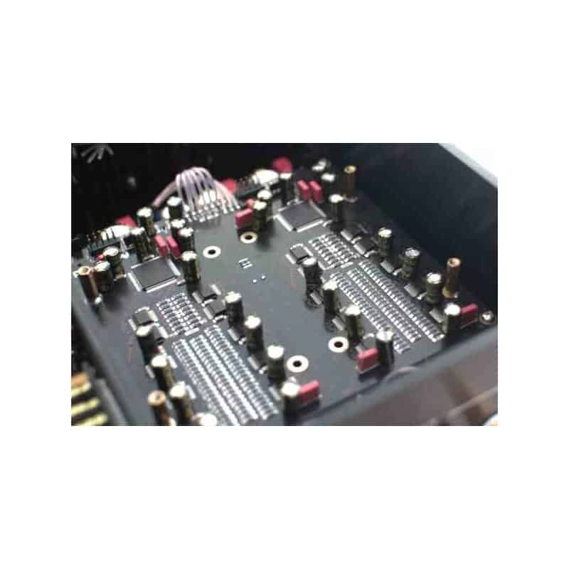
The R-2R DAC has become popular and was originally designed long time ago by MSB, and did not include the wonderful correction design of the modern MSB technology. In the High-End of the shelf (finished products) market, the R2R design is usually much more complex when outstanding performance is offered. Some manufacturers are using shift registers design to realize ladder compensation. A less complex, unfortunately also a less performing.
A far better design switches resistors in parallel mode; an ultra-fast FPGA chip controls and corrects the R2R ladder. The parallel design mode controls every bit respectively and therefore achieve unprecedented performance. (In parallel mode only 1 clock cycle is needed to output all data; serial design mode needs at minimum 8 up to 24 clock cycles) The parallel design is particularly complex, however when it is done properly it can correct every bit of the ladder. (Photo below shows a FPGA design with R2R ladder). With incredible speed and accuracy the R-28 will correct the unavoidable imperfections of the basic R2R ladder caused by tolerance of resistors; avoid glitches at ultra-high speed to deliver unrivaled musical performance.
TOLERANCE OF RESISTORS IN LADDER
Some manufactures claim to achieve good performance becuase they use lowest tolerance ladder resistors. The following calculation example will cover this. At 16 bit the tolerance of 1/66536, 0.1% (1/1000) it is by far not enough to achieve decent performance. Even using resistors with 0.01% (1/10000) tolerance, lowest tolerance available today,cannot deliver the desired performance This is just 16 bit, imagine a 24 calculation! To process 24 bit resolution it would require resistors with a tolerance of 0.00001%. This is purely theoretical; if this tolerance would exist the discreteness of the switch logic chips will already have too much internal impedance and will shake-up such design.The tolerance of the resistor will never solve Imperfections of a ladder.
The solution lies in the correction the ladder and not only depend on the tolerance of resistors. It’s a combination of both: Ultra-low tolerance resistors controlled by a correction technology using very high speed with parallel FPGA processing.
ULTRA FAST SIGNAL PROCESSING
FPGA stands for Programmable Array Logic. Nowadays the FPGA is widely adopted in audio devices. The internal hardware design is fully controlled by complex software. A huge advantage is the fact the software in the FPGA can easily be upgraded offering new capabilities or improve the performance of the device without replacing any hardware. Versatile and future proof design.
-
- High performance SPDIF interface, replacing traditional less good performing SPDIF interface chips like DIR9001, WM8805 or AK411X,etc.
- Full re-clocking process with FIFO design applicable on all inputs. This way the output data keeps fully synchronized with the clock signal to reject any jitter.
- Built in 2X, 4X and 8X oversampling and digital filters and on top of this 4 different true NOS (only analog 6dB filtering) modes. To completely configure the sound according to your taste.
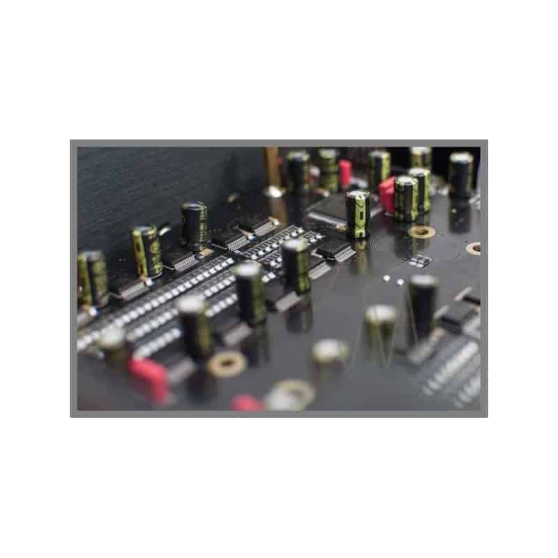
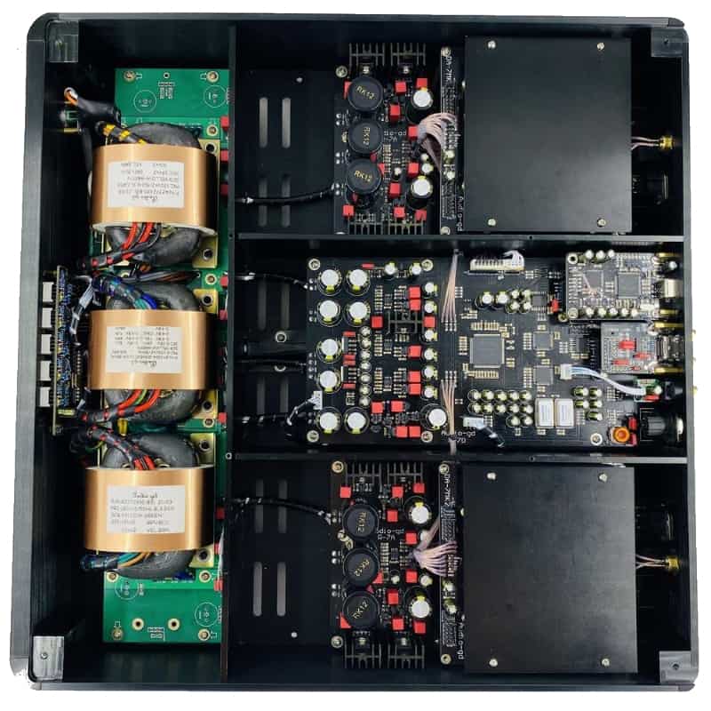
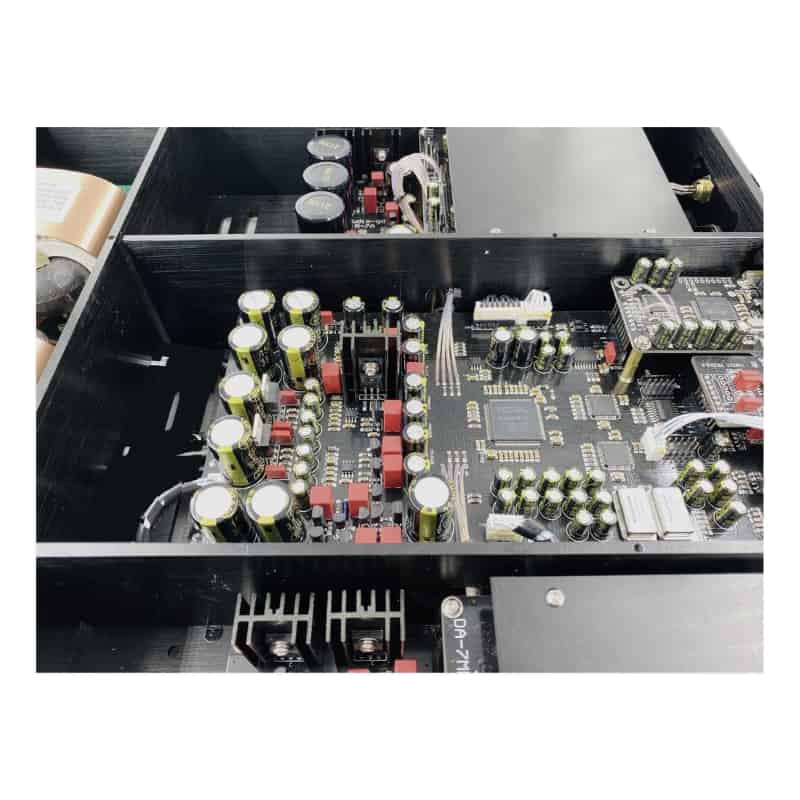
DISCRETE ANALOGUE OUTPUT STAGES
The analog output stages are as important, they have a tremendous influence on the final sound quality. After d/a conversion by the R2R D/A modules the analogue signal is transported by fully discrete matched-transistor output stages; DC-coupled design with first class through-hole components. No SMD compon ents are applied in the analogue section. The high speed unique ACSS ((Audio-gd Current Signal System) output stages are non-feedback and current driven. Unique performance because almost all other designs need to convert the signal multiple times from and to current and/or voltage, resulting in less detailed and less transparent sound-stage The output buffers are single ended FET; two stages in parallel to reach very low output impedance. All output stages are in pure class A without (negative) feedback to achieve purest and a real live sound reproduction. The 4 OPA op-amp’s are DC servos, this way no coupling-capacitors are needed and DC output is automatically biased. The listener will be presented a strikingly transparent and neutral sound.
ACSS – Current Amplification
Audio-GD has developed an advanced current-driven amplifier technique. Also known as ACSS, Audio-GD Current System Signal. This special technique ensures that the signal travels a much shorter path and that ensures a more transparent, faster and more neutral reproduction. A similar technique is used by, for example, KRELL. The Current Conveyor technology mostly components are the current mirror. The Current Conveyor technology isn’t a new technology, at 1966 , professor K.C. Smith and A.S.Sedra publish the concept “current mode analogue circuits “ .
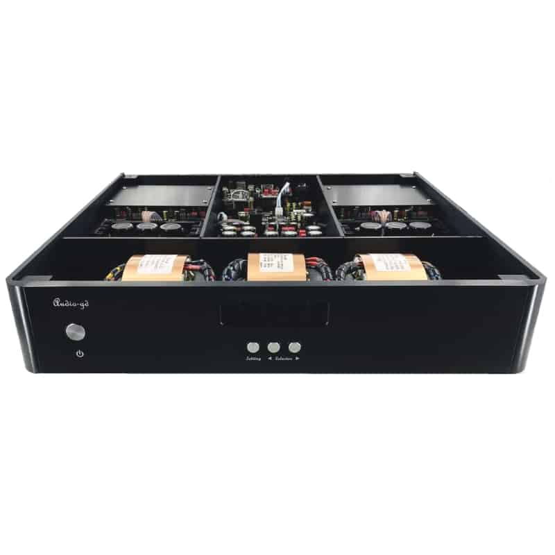
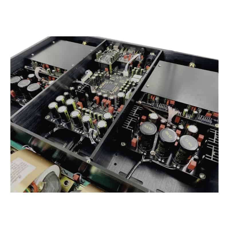
CLEAN POWER
The DAC consist of 3 tuned low noise, low flux leakage, R-cores transformers. In total 130W power to supply all digital parts and the left and right analog boards. The DC power is distributed over 19 separate power regulators. All are pure class A low noise shunts; fed by 3 groups linear power supplies. Resulting in ultra-high speed and clean power for all individual parts
FEATURES OF MK2
- Newly designed discrete servo stabilised power supply to power the digital circuitry, the noise level is comparable to that of a battery, but without the dry and thin noise characteristics.
- Newly developed analog vinyl configuration can be set via the menu. (New function)
- Both the USB and HDMI inputs are equipped with isolators and two sets of linear power supplies to power the USB and HDMI modules separately to avoid interference from signal sources.
- USB uses a two-way transmission isolator, which not only sends IIS signals to the FPGA processor, but also receives the synchronous clock signal sent by the FPGA processor.
- The USB interface itself is no longer equipped with clocks. The synchronous clock is adopted to make the signal transmission more accurate and upgrade the sound quality to an excellent level.
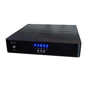
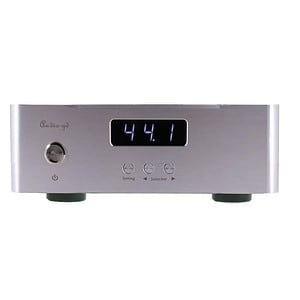
- Display sample rate of input source
- The 10MHz clock input allows the use of an external reference clock generator
- The FPGA works in parallel data processing mode.
- Listening comparisons taught us that parallel processing mode makes the sound clearer and more neutral, with better dynamics and a more analog taste.
- The clock management design of the new architecture makes the clock work more stable, bringing more transparency and more details.
- DSD uses the built-in asynchronous clock to improve the timing, which clearly improves the clarity and dynamics of reproduction.
| Gewicht | 16 kg |
|---|---|
| Größe | 430 × 430 × 93 mm |
| Brand |
Nur Bewertungen auf Deutsch (0) anzeigen
Schreibe die erste Bewertung für „Audio-GD – R7 MK2 – Discrete Balanced R2R Ladder FPGA Accusilicon DAC – PCM / DxD / DSD“
Worldwide Shipping
![]()
- Customers outside European Union pay price excluding VAT (Custom fees maybe applicable)
- Services and delivery options are automatically calculated at checkout.
- We ship with DPD, DHL, UPS or Fedex. (Specify preferred shipper in order note)
- In some situations a preferred shipping company might involve additional costs. We will contact you.
Payment options
- We accept many payment methods, including major credit cards (Visa, MasterCard, Amex), PayPal and Apple Pay and many other’s.
- In some countries we support Klarna slice-it or 3 - instalments
- When you would like to pay with credit card above 5000 EURO we make 2 or more instalments. Contact us please.
Ähnliche Produkte

R-2R DISKRETE LEITER-DACS

R-2R DISKRETE LEITER-DACS
Audio-GD – R27 mk2 – Regenerative PSU Balanced R2R PCM / DxD / DSD – Vor- & Kopfhörerverstärker
Vorrätig
R-2R DISKRETE LEITER-DACS
Vorrätig

R-2R DISKRETE LEITER-DACS

R-2R DISKRETE LEITER-DACS
Audio-GD – R1 2021 – Diskrete symmetrische R2R Ladder FPGA DAC – PCM / DxD / DSD – 2x Akku
Nicht vorrätig
R-2R DISKRETE LEITER-DACS
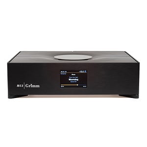
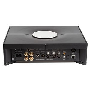
GRIMM AUDIO – MU2 – Ultimate digital music source with DAC and Roon Server integrated

R-2R DISKRETE LEITER-DACS
Audio-GD – R28 NOS – Diskreter R2R DAC – Vorverstärker & Kopfhörerverstärker
Vorrätig

R-2R DISKRETE LEITER-DACS
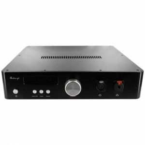
Audio-GD – R27HE – Regenerative PSU Balanced R2R PCM / DxD / DSD – Pre- & Kopfhörerverstärker
Vorrätig
Bewertungen
Es gibt noch keine Bewertungen.